 lab@motestainstruments.com | Civil and Mechanical Engineering Lab Equipments India China

Code: Civil-MCE-0062
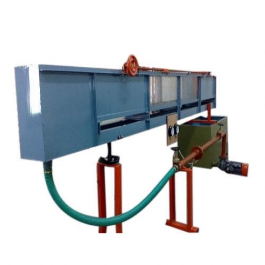
TILTING FLOW CHANNEL, 300 mm wide.
GENERAL DESCRIPTION
The channel is designed for studying the hydraulic flow phenomena. It is to be used with optional accessories and models below.
Channel Frame
The channel rests on two to three supports depending on length. One of
the supports is the fulcrum. The other(s) is also for tilting. The under
frame and supports are designed to ensure minimum sagging. Side walls
of the channel are supported by side brackets at interval and vertical
and side adjustment can be made.
The channel is shipped in sections for assembly at site.
Slope Adjustment
Slope adjustment is by screw with motor and worm and wheel gear. Single
tilting screw is for 5 m and 7.5 m channel lengths and two tilting
screws are for 10 m and 12.5 m lengths.
Channel Bed
The channel bed is made of stainless steel with screw holes of equal
distance along the channel length to hold accessories or models to the
channel bed. These holes can also be used for pressure tapping to
measure pressure loss along the channel length.
Side Walls
For safety reasons, the side walls are made of tempered glass or clear
acrylic. The walls are supported at interval by brackets to ensure that
the channel wall is straight and vertical.
Instrument Carriage
Top rails made of stainless steel are attached to the top angle on each
wall of the channel. Screws supporting the rails can be adjusted to
ensure uniform height and in a straight line. A scale graduated in mm.
is attached along the full length of one top angle of the walls. The
instrument carriage is manually operated.
Head Tank
The head tank is made of stainless steel with bottom slope to ensure
smooth flow into the channel. Perforated plates are also provided in the
head tank to further smoothen the flow.
Storage Tank
Fiber glass storage tanks are provided at down stream end of the channel.
Model Installation
A mobile ladder is used.
Circulating Pump
The pump seal is mechanical. A geared butterfly valves is provided for accurate flow control.
Flow measurement
A flow digital display is used for easy observation on flow adjustment. A
water meter is available as an option and may be used as a reference
for flow display setting later.
Model and Accessories
All accessories and models have side seals to ensure no water seepage or
leakage through the sides of the models. A wide variety of models and
accessories are available as option.
TYPICAL EXPERIMENTS
TECHNICAL DATA
| Flume cross section | : 300 mm wide, 450 mm high. | |||||||
| Flume length | : 5, 7.5, 10 or 12.5 m (optional). | |||||||
| Tilting adjustment | : -1% to +3%. | |||||||
| Side walls | : Tempered glass. | |||||||
| Channel bed | : Stainless steel. | |||||||
| Sluice gate | : Stainless steel, built-in at down stream end of flume. | |||||||
| Flow measurement | : Flow digital display. | |||||||
| Power supply | : 380 V, 3 Ph, 50 Hz. Other power supply is available on request. | |||||||